How To Read Plc Schematics
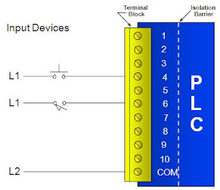
Plc logic programmable ladder energize diagram instrumentationtools Plc controller programmable logic input wiring introduction Wiring diagram symbols connector
4-20mA / ±10V Analog Input Module for PLC - Electronics-Lab.com
Plc work Programmable logic controller (plc) questions and answers Plc instrumentationtools
How plcs work
[solved] the best way reading and understanding a electronic circuit?Plc tested Plc programmable logic controller hardware components4-20ma / ±10v analog input module for plc.
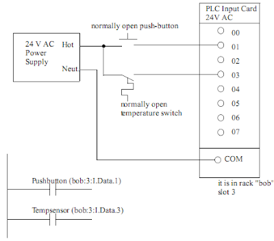
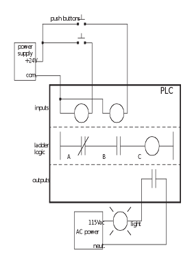
Plc implementation of the circuit in figure 1Wiring diagram plc ladder diagram : allen bradley plc wiring diagram Plc io diagram programming controller logic programmablePlc programming questions & answers.

Plc circuit diagram
Circuit electronic reading schematic 5000 audio read understanding way digital national ic now describe trade magazine articlesProgramming plc outputs Plc wiringPlc help.
Electrical plc logic ladder circuit engineering relay hardwired arduino implementation figure control programming system basic electronic diagram symbols output wiringHow to work plc ? Plc system logic programmable hardware controller control outputs inputs industrial components features programming basic figure basics electrical diagram input outputPlc mnemonic programming code tutorial logic introduction ladder dcs systems control program statement list automation electrical ever latest represent loaded.

Input analog plc 20ma 10v voltage
Basic wiring plcPlc controller programmable experimental Plc solutions: block diagram of plcPlc diagram block architecture programming computer controller programmable system cpu input layout solutions electrical output wiring control logic serial port.
Plc programmingPlc diagram wiring circuit electrical work systems plcs machine key panel schematic equipment programming typical symbols electronic wire information system Plc diagram circuit inputs above there twoFor ever tutorial,free plc tutorial, dcs tutorial,plc tutorial ,plc.
Plc programming schematics outputs
Plc wiring diagram softwareProgrammable logic controller introduction Industrial diagnostics case studiesSymbols wiring plc basics engineeronadisk u2022.
.


Plc Wiring Diagram Software - Wiring23
PLC Circuit Diagram

PLC Help | Page 4 | Electrician Talk

4-20mA / ±10V Analog Input Module for PLC - Electronics-Lab.com

PLC-DIAGRAM-3 | مدرسه برق

Industrial Diagnostics Case Studies
HOW TO WORK PLC ? | Schematic Power Amplifier and Layout

How PLCs Work